Electrical and Hydrogen Microgrid - Energy Control of a Self-Sufficient Supply System Based on a Combined Electrical and Hydrogen Distribution Grid
The self-sufficient microgrid consists of the feed from renewable energy systems, the electrical network and the H2 gas network with a liquid or gaseous energy source. In contrast to an island grid, the microgrid can be operated in parallel with the grid. The associated challenges of transient energy flows, as well as the holistic view of a regulated microgrid based on an electrical network and an H2 gas network, are part of this article.
For the success of energy transition and the reduction of CO2-greenhouse gas emissions, the distribution and storage of electrical energy within the framework of a microgrid will play a key role in the future energy supply. A purely capacitive network expansion in Germany is only one element of the energy transition and must be expanded to include the conversion of the current central network, with a central control system, to a decentralized network with intelligent control units. With an increasing share of renewable, decentralized units for power generation, such as photovoltaic or wind power plants in the energy mix, location-based island grids that function as microgrids can make an important contribution to the supply security. Excess electricity is more variable and better regulated even at the smallest site-specific level. The remaining fluctuations from the microgrid steadily decrease via the distribution grid to the transmission grid. Wherever possible, the microgrid can also be used as an autonomous and self-sufficient system for regional district supply. Microgrids are independent supply areas that have special operational management requirements and can be connected to the public grid. In the context of this article, the microgrid is the interface between the electrical grid and the grid with a liquid or gaseous energy source (Figure 1). At present, it can be assumed for the near future that energy generation from renewable energy sources cannot be fully stored as electrical energy, so that a transportable additional medium, like hydrogen, is needed that can be easily stored and further converted as needed. The associated problems, such as the holistic view of a microgrid based on an electrical part and a hydrogen network, are part of this article. This is based on the EFRE project “Wasserstoff – grünes Gas für Bremerhaven“, in which a microgrid is being set up in order to be able to supply the Lune Delta area in Bremerhaven with self-sufficient energy in the future.
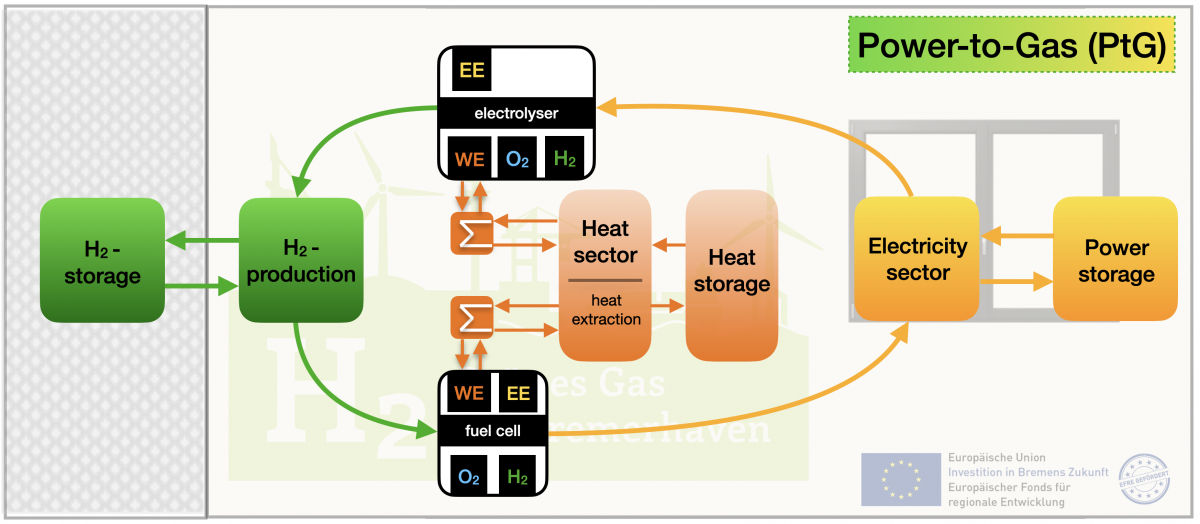
Figure 1: Sector coupling of the microgrid container at the Bremerhaven University of Applied Sciences.
System structure of the microgrid
The microgrid is fed exclusively from renewable energy sources such as photovoltaics and wind turbines and, as a “topological power plant” (VPP), can also provide the higher-level electricity grid for system stability (Figure 2). Active and reactive power control is also mapped. Such system services help to partially replace conventional power plants. In addition, the performance of the renewable energy producers can be reliably forecast, intelligently planned and controlled via the control technology. Central points of the system are the production and storage of hydrogen as a chemical energy carrier with the help of renewable energy sources and the reconversion of hydrogen into electrical energy with the help of a fuel cell. This is initially done on a small scale and is later scaled up to the energy requirements of the green industrial park “Lune Delta”. The power grid of the microgrid consists of two main voltage levels: the 48 V DC level at the output of the fuel cell for the battery storage and the 400 V AC (three-phase level) for the feed-in of renewable energies. The grid connection point is a switchable connection between the microgrid and the higher-level power grid. The 48 V DC is converted using a DC-AC inverter and a rotating converter. The hydrogen is generated with a PEM electrolyser which can be fed via a 400 V or 48 V busbar. The hydrogen produced exits the electrolyser at 16 bar and is temporarily stored in a low-pressure storage device. The hydrogen from the low-pressure tank is compressed to 200 bar using a hydrogen compressor and is then stored in the high pressure storage tank. Intermediate storage of the hydrogen is necessary because with the same electrical power data of the electrolyser and the fuel cell, the hydrogen generated is not sufficient to achieve the same performance through reconversion at the fuel cell output. At this point, the effects of the feed-in of fluctuating renewable energies on the electrolyser and the associated pressure fluctuations in hydrogen production are examined. The extent to which a decoupling from the feeding energy sources is possible is being researched. The microgrid was examined in advance with a simulation program as a basis for system development.
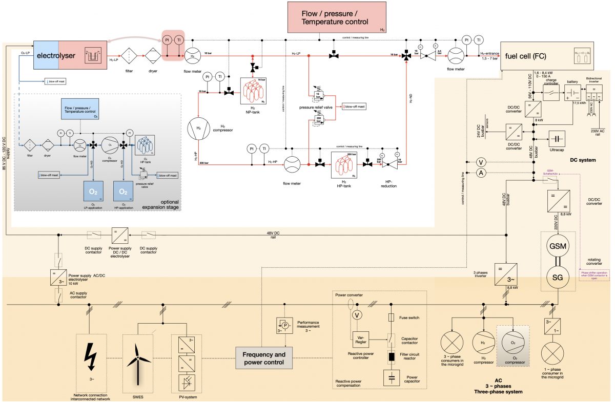
Figure 2: Schematics of the whole system structure
Hydrogen distribution grid
The hydrogen distribution grid consists of three pressure levels (Figure 2 – top left). The hydrogen leaves the electrolyser at a pressure of 16 bar and is fed directly into the central pressure piping system H2-LP (16 bar). Here the hydrogen can be stored in a low-pressure system and, if necessary, brought to a higher-pressure level H2-HP (200 bar) with the help of a pneumatically driven hydrogen compressor. The hydrogen is stored in a bundle of 6 gas cylinders at 200 bars and, if required, can be expanded again to 16 bar via the HP reducing valve and fed into the central pressure piping system H2-LP (16 bar). The inlet pressure of the fuel cell determines the third pressure range of the hydrogen network of the microgrid H2-LP (4.5 bar). Since the fuel cell does not have a fixed inlet pressure, but describes a pressure range from 1.5 bar to 7 bar, an average inlet pressure of 4.5 bar was determined. On the one hand, falling below 1.5 bar would result in the fuel cell being switched off; on the other hand, exceeding 7 bar would damage the fuel cell. Pressure relief valves were installed within the 20 bar and 200 bar pressure piping sytems to protect the pipes and components. In the lowest pressure level H2-LP (4.5 bar), no pressure relief valve is provided due to the low pressure and the regulated pressure reducing valve. Temperature, pressure and flow measurements are integrated in all three pressure levels so that the measured values obtained can be used to control the microgrid. In addition to sensors, solenoid valves are also used to control the flow of hydrogen.
Power distribution grid
The power grid of the microgrid consists of several voltage levels and offers two options for converting the 48 DC V at the output of the DC-DC converter into 400 V AC (Figure 2 – right-hand side). Since a voltage drop on the part of the fuel cell is to be expected, an output voltage range was specified. When idling, the fuel cell has a DC voltage of 110 V, which drops to 56 V at full load. The DC-DC converter connected to the fuel cell ensures that the fuel cell feeds the 48 V busbar with constant voltage. The 48 V busbar forms one of two main busbars and offers the option of integrating a battery, a supercapacitor (UltraCap) and a bidirectional inverter. With the help of the bidirectional inverter, it is possible on the one hand to generate two 230 V AC connections via the 48 V busbar or the battery, on the other hand it is also possible to charge the battery via a 230 V main grid connection. This is an advantage when commissioning the microgrids. The microgrid has two options for generating three-phase alternating current. The consideration of the feed-in behavior of inverters and rotating converters should provide insights into reactive power compensation, control behavior, network quality and system stability. One has the choice between a converter-fed three-phase grid and the generation of a three-phase grid via a rotating GSM-SM machine set. An intermediate voltage of 220 V DC is required for the direct current machine (GSM) of the rotating converter. This is the only way to ensure that sufficient power is available for the conversion. Other DC consumers can also be connected to this 220 V DC system. The 400 V three-phase busbar connects the feeding renewable energy sources, such as the photovoltaic system and the small wind turbine, with the electrolyser. The pneumatically operated hydrogen compressor is supplied indirectly via the 400 V AC busbar. In order to ensure variable and trouble-free operation of the electrolyser, it can be supplied via the 48 V and 400 V busbar. Among other things, this offers the opportunity to conduct studies in the direction of electrolysis power supply and to demonstrate its advantages and disadvantages.
Control of microgrid energy distribution
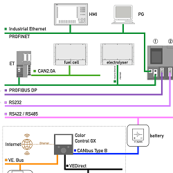
The control challenge is to connect the different components of a microgrid so that they can communicate with each other (Figure 3). Complete control of the microgrid is only possible if all components are interconnected via a common central regulation/ control unit. The basic regulation of the microgrid consists of a centrally located programmable logic controller (PLC) and a decentralised ET. The communication between sensors, actuators and PLC can be done via analog input/output modules. The charge status of the 48 V battery can be queried via an RS485 module. The entire control system is configured and programmed via Siemens TIA Portal. During operation, a Human Machine Interface (HMI) is used to visualize the process data and to control the energy management. Data or measured values are obtained from the electrolyser via a PROFINET connection. The ET used has the task of converting the data records obtained by the fuel cell from the CAN2.0A BUS into the existing PROFINET network. This leads to simplified wiring and decentralised data processing within the microgrid. The data can be read out locally and transferred to the PLC via PROFINET. The use of PROFINET also simplifies the parameterisation effort compared to PROFIBUS. Despite the disadvantages of PROFIBUS, an interface was provided on the PLC to ensure downward compatibility with older drives and components. The university's microgrid is variable for follow-up projects and can adapt to changes. The digital input modules are used for different manual pushbuttons and switches that are relevant for the operation of the plant. The digital output modules of the PLC are used to activate warning/signal lights inside and outside the container. The components for battery management are located on the lower left side of the screen within the dotted line. This control runs parallel to the PLC but has a common interface to the battery. In addition, the bidirectional inverter in this system enables pre-charging of the battery storage to facilitate commissioning of the microgrid after an extended shutdown or during initial start-up.
Operation draft of HMI and system integration
The operational draft of the system communication describes the interfaces of the microgrid control. The operating structure was implemented in the HMI according to figure 3.
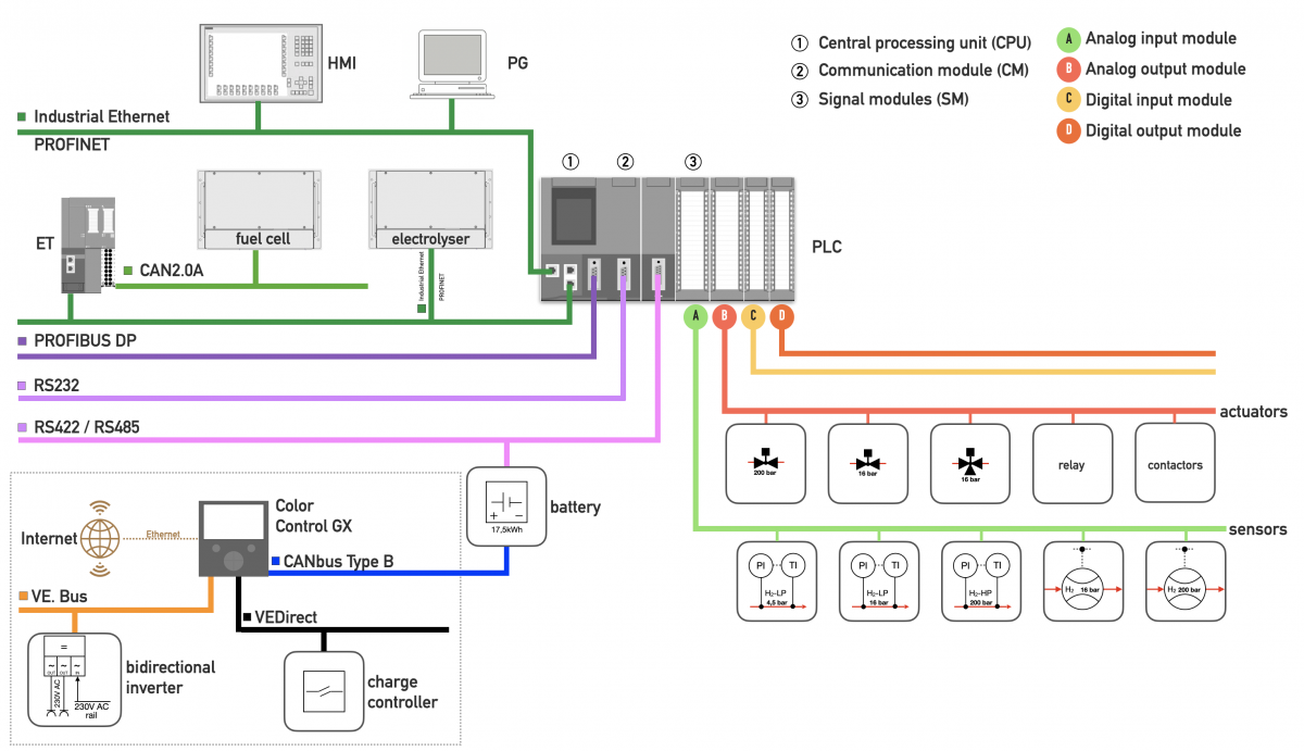
Figure 3: Operation draft of communication structure and HMI.
The focus was on the clear structuring of the microgrid and its main components. The HMI should clearly display and control the microgrid and be able to show the user the faults as quickly as possible in case of malfunctions. This requires a communication structure based on real-time mode. All sensors and actuators are connected to each other via different communication protocols and interfaces (Figure 2). The start screen of the HMI leads you to three main submenus of the initialized controller. The Construction Container menu includes all control and monitoring of the microgrid container. All HMI system-relevant displays and menus are located under the system images (based on figure 1). All-important alarm messages and status displays, such as the hydrogen detector, are located under the safety system tab. This allows the user to access the three most important submenus directly from the start screen. This helps the users to quickly find his/her way around the operation of the microgrid and faults can be rectified quickly. The construction container area is structured according to its energy sectors. The microgrid consists on the one hand of an energy area (electricity area) and on the other hand of a gas area, which is realised by the hydrogen.
Energy management
The microgrid is fed from renewable energy sources, which are the prerequisite for the production of green hydrogen. The renewable energy sources are fed into the 400 V busbar of the microgrid. There, the electrical energy obtained from wind and sun is combined and fed to the electrolyser. Depending on the available electrical energy, hydrogen is produced. The hydrogen can then be stored in a low-pressure or high-pressure storage tank. In the gas sector, the two hydrogen storage systems represent a variant of energy storage. In the electricity sector, battery storage systems are used for long-term storage and supercapacitors for short-term storage of electrical energy (Figure 2).
The electrolyser is the link between the electricity and gas sectors. The fuel cell converts the energy contained in the gas back into electricity. This leads to a coupling of energy sectors in energy management with its advantages and disadvantages. The supercapacitor is to compensate for the high starting currents of the rotating converter and thus keep the voltage stable. The battery storage is used to buffer electrical energy in the event of fluctuating hydrogen production or to bridge empty hydrogen storage tanks.
Reactive power control
The microgrid at Bremerhaven University of Applied Sciences supplies reactive power to support the grid voltage in island mode. It has the option of performing a black start in island mode. The microgrid has two different types of reactive power control and compensation (Figure 1). The harmonic type of reactive power control is carried out via the rotating converter. The clocked type of reactive power control is carried out via the power electronics on the 400 V busbar. The primary control (also called secondary reserve) is used to control the frequency and the active power. Secondary regulation is used for voltage regulation and also for reactive power compensation.
A positive effect of the rotating converter is the possibility of power factor correction in phase-shift operation of the synchronous machine. As mentioned before, the microgrid has two options for feeding the electricity from the fuel cell to the 400 V AC busbar. This can either be done via the 3-phase inverter or via the rotating converter. If the feed is via the first option, the contactor to the DC machine can be opened. This means that the DC motor is no longer supplied with voltage. The connection to the 400 V AC busbar remains on the other side of the rotating converter. In this case, the generator is operated as a phase shifter and rotates with the 400 V busbar at the mains frequency of 50 Hz. The reactive power can be regulated via the excitation of the synchronous generator. However, it must be considered that the DC motor is also driven and the synchronous generator in phase-shifting operation cannot deliver or absorb pure reactive power, but must also generate active power. This leads to a reduction in the energy obtained from the reconversion of the fuel cell. The advantage, however, is that no additional components for reactive power compensation have to be inserted into the microgrid. With the second option of feeding the 400 V AC busbar via the rotating inverter (contactor left path open, right path now closed), there is the option of reactive power compensation via excitation of the synchronous generator.
Dieser Beitrag entstand im Rahmen des Teilvorhabens „Microgrid“ der Hochschule Bremerhaven, das im Gesamtvorhaben „Wasserstoff – grünes Gas für Bremerhaven“ aus Mitteln des Europäischen Fonds für regionale Entwicklung (EFRE) gefördert wird.
Schlüsselwörter:
green energy, hydrogen, microgrid, renewable energy sources, rotating converter, DC, AC, energy managementLiteratur:
[1] Werner, U.; Fichter, C.: A Comparison of Future Alternative Fuels (LNG, Hydrogen) Utilizing in Maritime Passenger Ships for Heating, Electric Power Supply and Ship Propulsion. 6th International Cruise Conference ICC. Bremerhaven 2019.
[2] Salomon, S. D.; Werner, U.; Fichter, C.: Projektierung und Modellierung eines Microgrids zur autarken Energieversorgung auf Basis eines kombinierten elektrischen Verteilernetzes und einem Wasserstoffnetz. VDE-ETG-Kongressbeitrag 2021.